LCD Master 3D
3DCAD
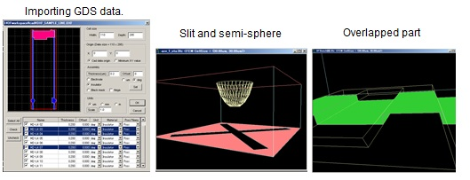
Whole 3D structure is defined as assembled small 3D parts. By adding thickness to 2D figure it can define 3D part. Slit and slope also can be defined to the 3D part. Each 3D part can be overlapped each other that can make more complicated 3D part. It illustrates 2D figure by 2D CAD system and it imports the 2D data in GDS or DXF format. There is no difference about the operation between FEM and FDM.
Director
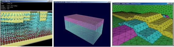
The action of the liquid crystal molecule (director) at the time of impressing voltage is calculated. At Dynamic analysis, a time response is calculated and the equilibrium state in specification voltage is calculated by Static analysis.
Both FEM and FDM have dynamic and specialize static solver respectively.
LCD Master/3D static solver can calculate ten times more faster than conventional algorithm.
As V-T characteristics can be gotten with very short time, it is easy to do optimization with 3D structure. Neumann, Periodic, Mirror symmetry and Wall boundary conditions are available.
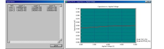
Capacitance
Electrical capacitance between arbitrary two electrodes can be calculated after director orientations have been solved.
Weak anchoring
Anchoring energy on the upper and lower LC boundary can independently be specified in azimuth and polar angle.
PSA analysis (FEM only)
1. The state of alignment is obtained from the condition for an initial alignment.
2. To the upper and lower layer thicknesses are fixed by the state of alignment obtained by 1, and perform static calculation at 0V.
3. Actual calculation is performed by fixing the upper and lower layer thicknesses, when the initial alignment is the obtained state of alignment by 2.
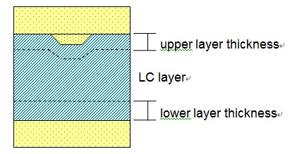
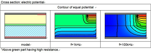
Statics with AC assumption (FEM only)
Applied voltages used in static simulation are defined as R.M.S (Root Mean Square).
R.M.S affects static simulation results but driving frequency never been considered even if actual applied voltage was alternative current (AC). This conventional static simulation is called, here after “DC Statics”. When all substances in analysis field are insulators and conductors, “DC Statics” outputs correct results which correspond with physical phenomena.
On the other hand, driving frequency affects the results if conductive substances are contained in analysis field. This new type statics considering not only R.M.S but also electric conductivity is called, here after “AC Statics”. Difference of electric conductivity and driving frequency make different electric field which makes different LC director distribution.
Thus different director distribution is induced by different electric conductivity and driving frequency even if R.M.S is even.
The above conclusion suggests that lower voltage driving LC device can be developed by considering electric conductivity and driving frequency and by using “AC Statics” simulation, but, of course there may be opposite possibility.
1D file output
The director distribution calculated by three dimensions can be passed to one dimension, and optical calculation combined with the polarizing plate and the retarder film can be performed.
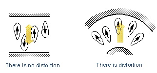
Flexoelectric effect
Flexoelectric effect is also supported which is observed as
electric polarization when such splay or bend distortion occurs.
By specifying Flexoelectric coefficients e1 an e2, it can show
more close real time-response or n-directors distribution.
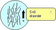
Tensor order parameter (FDM only)
The analyzing algorithm is like a microscopic simulator by using
order parameters. The Q tensor can reveal not only n-directors
direction but also scalar order parameter time change and spatial
distribution. SHINTECH uses most rigorous theoretical formulae,
different from de Gennes or Berreman’s Q-tensor explication,
which is the first commercial simulator in the world!
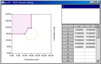
Multi-domains cell
Two or more domains are specified and different initial director conditions (Pretilt, Twist) can be specified.
Floating (FEM only)
The constant source of voltage is usually connected to a metal electrode, and the potential becomes settled. On the other hand, although it is a perfect conductor, since it does not connect anywhere, the electrode with which potential does not become settled is called Floating electrode. It is used when Black mask is realized by chromium, and this is modeled.
Electric charge (FEM only)
In the charge drive analysis, it calculates on the condition of a constant voltage and a constant electric displacement.
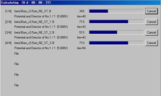
Parallel processing
Multiple files can be simulated successively. In such case LCD Master/3D supports parallel processing. However it spends much memory area, the 64 bits OS is recommended.
3D Optics
The multilayer film definition of the light element registered into the database is carried out, and the light which spreads the inside of the structure is calculated. There are two of the 2 x2 methods which considered reflection as the 4×4 method for having taken multiplex interference into consideration as an algorithm once.
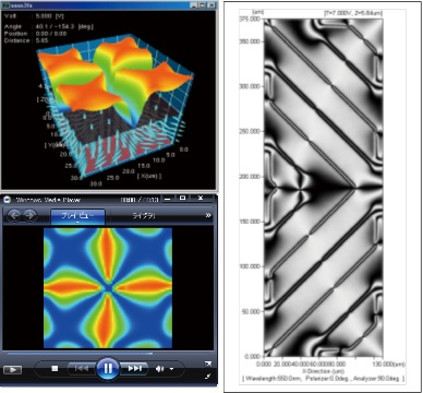
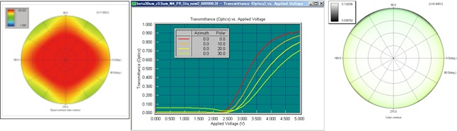
Optical calculation in bulk (2×2 or 4×4)
The transmissivity to the perpendicular incidence light in Bulk is calculated by the 4×4 matrix method or the extended Jones matrix method, and it indicates by graphic as a distribution map. Moreover, it is also possible to display T-T graph based on the transmissivity in the saved time.
Transmission, reflection (2×2 or 4×4)
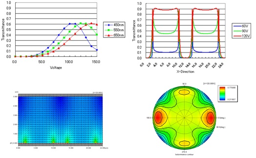
In the 3-dimensional calculation, spatial distributions of the director are calculated moment by moment as shown in the structural model below.
For the acquired director distribution, this option performs the calculation for the light passing through a cell as indicated by the arrow in the figure below. For electrode and dielectric layers other than liquid crystal, either isotropic materials or complete absorbers must be specified. When isotropic materials are specified, their refractivity and absorptivity are taken from the specified LCD Master database. For optical elements other than electrode and dielectric layers, Black Masks can also be defined at the top of the cell as necessary. In addition , the calculation can also be performed by aligning polarizers and phase compensation films, entered with the basic system, above and under the cell.
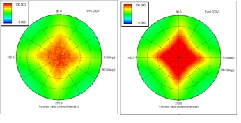
For the optical model defined in the above manner, an optical calculation will be performed with either the 2×2 or 4×4 algorithm. Since data can be scanned in the X-axis direction at each observation point, the distribution of the transmissivity in the X-axis direction can be obtained. In addition, since the azimuth and polar angle direction can be scanned, iso-luminance contour at that point can also be observed.
This calculation can be performed independently for each user-defined time data. For example, equal contrast contour can be observed for the spatial average of transmissivity at the OFF time and the ON time by acquiring the ratio between them.
Mueller matrix
Newly an optical calculation function by Mueller matrix is added in .Ver.8 to the conventional optical calculation which was expressing polarization propagation using Jones matrix.
By the new optical calculation by Mueller matrix, Ver.8 has the following new functions.
・De-polarization simulation can be done.
・Partial polarized light can be handled in the incidence polarization.
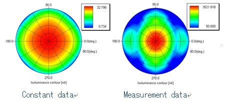
・The actual data measured by OPTIPRO can be inserted to the database and calculated.
・The polarization data of the light source measured by OPTIPRO can be specified as an incidence polarization.
Metal reflector
In addition to ideal mirror it simulates reflective LCDs with metal reflector.
Customers can take more reliable final optical performance of the reflective LCDS.
3DTV evaluation
It can stack optical materials at the observational point as an observational panel as well as conventional LCD panel defined on the basis of the absolute coordinate.
Especially it is very useful for design 3D TV eye-glasses. You can estimate the final optical quality via the eye-glasses by this function. As the observational panel can be saved into a disk as a sub-structural data, you can evaluate the performance in combination with other conventional LCD panel immediately.
Import measured luminance data
Measured luminance data can be imported as light source data.
Import ray-tracing data
Spectroscopic characterization and incident angle dependency of the backlight can be disregarded to evaluate total performance of LCD. Optical solver calculates Transfer matrix and input light polarization will be multiplied to the matrix.
T=[M]A
Both T and A are vectors, T is output light, A is input light polarization vector. M is the transfer matrix which can be represented as Jones or Mueller matrix. A becomes Mueller matrix when A is partial polarized light and becomes Jones matrix when A is perfect polarized light.
Ray tracing software, like SPEOS or LightTools* generates A which can be imported to LCD Master/3D and output T.
Ray tracing software cannot figure out TV size light guide because it takes terribly longer time. In such case LCD Master/3D can import measured data that are gotten by OPTIPRO (σ-meter). Imported data are converted to A. Sometimes by changing light guide design final contrast improved several times more that is very attractive for the designers who want to get good final optical performance.
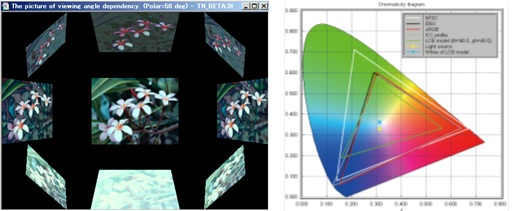
Evaluation by image
Optical results are evaluated with a portrait or landscape photo. This evaluation is more understandable than by numerical characters. A look of LCD by changing γ parameter can be recognized intuitively.
To check color gamut R, G and B color filters are chosen. You can know the current LCD model has how much color gamut comparing with NTSC or sRGB.
To display the image more realistic ICC profile is supported. ICC profile represents the display γ characteristics. LCD Master/3D reads ICC profile to know what PC monitor was used. In next stage, to display with more realistic color LCD Master/3D modified results to match the PC monitor.
Blue phase LCD analyzing
We developed a new software package for modeling the electro-optical response of blue phase liquid crystal displays (BP LCDs). The package, solving numerically the potential equation, finds the electric field that is generated by application of voltage to the electrodes in the BP LCD cell. Next it calculates the optical response or the polarization transfer characteristics of a BP LCD. We approximate the induced birefringence of BP LC by Kerr effect. The polarization transfer property is calculated numerically in the same way as in our LCD Master/3D package. Those results are shown graphically.
-The numerical calculations are carried out by the finite difference method in the three dimensional space.
(cross section of an LC cell)
-Optical characteristics such as a distribution of transmittance along the transverse direction are shown graphically.
-The viewing characteristics such as angular dependence of contrast ratio are easy to evaluate by the viewing cone.
-The model of BP LCD cells are able to be defined easily and quickly through drag and drop operation in the GUI.
Circuit editor, net-list output
LCD Master/3D can work with other SPICE simulator, NEXXIM for large size electrical circuit.
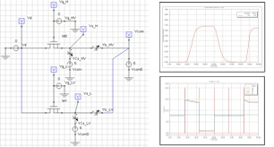
Integration with a circuit simulator
By supplying either voltage (V) or electric charge (Q) to each electrode electric potential at each discrete point is solved. Electric charge driving is better for getting actual response time, but it is slightly difficult to set Q for each electrode.
Then U.C. Berkeley version SPICE, 3F5 has been implemented to determine how much electric charge should be supplied. As in the schematic editor defines Cs and ohmic resistance for wire, it becomes more powerful comprehensive tool for analyzing high speed response.
For Splay or bend deformation dipole moment appears microscopically. FDM can consider such polarization effect; flexo-electric effect; to solve Poisson equation.
Export movie files
In dynamic case time variation, in static case voltage variation of like transmittance will be shown as movie.
Those movie data can be exported to AVI formatted file which is played by Microsoft Media Player and very useful for the presentation to customer or internal meeting.
More realistic transmittance variation is shown without experiments.