LCD Master 2D
Director
The action of the liquid crystal molecule (director) at the time of impressing voltage is calculated. At Dynamic analysis, a time response is calculated and the equilibrium state in specification voltage is calculated by Static analysis.
Dynamic
Calculates and visualizes the director orientation in a
two dimensional electric field generated by multiple
electrodes having different potentials.
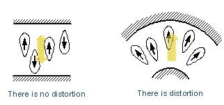
Facilitates estimation of the location of disclinations.
Provides a user friendly and intuitive graphical user interface.
Enables flexible, interactive modeling of LC cell including multiple
electrodes and insulators.
By auto-mesh generator you can obtain a meshed region and modify coarseness after mesh generation by clicking each point. (FEM only)
Static
The equilibrium state under the given voltage conditions is calculated. It can apply a fixed voltage or scanned voltages to each electrode. The scanning electrodes have both start and stop voltages. Static calculation is performed the number of times that is specified in calculation condition.
In FEM, calculation of conventional ratio 50 times is attained by a high-speed Static calculation solver, and a V-T curve can be generated in a short time.
Flexoelectric effect (EX)
Flexoelectric effect is also supported which is observed as
electric polarization when such splay or bend distortion occurs.
By specifying Flexoelectric coefficients e1 an e2, it can show
more close real time-response or n-directors distribution.
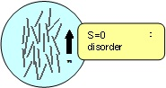
Tensor order parameter (EX)
The analyzing algorithm is like a microscopic simulator by using
order parameters. The Q tensor can reveal not only n-directors
direction but also scalar order parameter time change and spatial
distribution. SHINTECH uses most rigorous theoretical formulae,
different from de Gennes or Berreman’s Q-tensor explication,
which is the first commercial simulator in the world!
Multi-domains cell
Two or more domains are specified and different initial director conditions (Pretilt, Twist) can be specified.
Director distribution illustration
A result is displayed after the end of director calculation. A director expresses the direction in each lattice point on the stick or the nail (since direction is expressed). Transmissivity displays the transmissivity distribution in a specification sample. Potential distribution draws a equipotential line.
1D file output
The director distribution calculated by two dimensions can be passed to one dimension, and optical calculation combined with the polarizing plate and the retarder film can be performed.
Capacitance
Electrical capacitance between arbitrary two electrodes can be calculated after director orientations have been solved.
Floating electrode
The constant source of voltage is usually connected to a metal electrode, and the potential becomes settled. On the other hand, although it is a perfect conductor, since it does not connect anywhere, the electrode with which potential does not become settled is called Floating electrode. It is used when Black mask is realized by chromium, and this is modeled.
Weak anchoring
Anchoring energy on the upper and lower LC boundary can independently be specified in azimuth and polar angle.
Parallel processing
Director calculation will be automatically parallelized by using this function and consequently the calculation time can be drastically reduced.
Stable mode
It can re-calculate by specifying another conditions by making into an initial alignment state the state of director which calculated by dynamic analysis.
Optics
The multilayer film definition of the light element registered into the database is carried out, and the light which spreads the inside of the structure is calculated. There are two of the 2 x2 methods which considered reflection as the 4×4 method for having taken multiplex interference into consideration as an algorithm once.
Optical calculation in bulk (2×2 or 4×4)
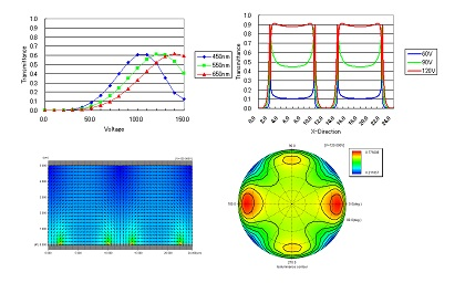
The transmissivity to the perpendicular incidence light in Bulk is calculated by the 4×4 matrix method or the extended Jones matrix method, and it indicates by graphic as a distribution map. Moreover, it is also possible to display T-T graph based on the transmissivity in the saved time.
Transmittance, Reflectance (2×2 or 4×4)
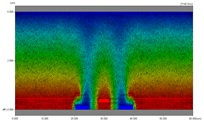
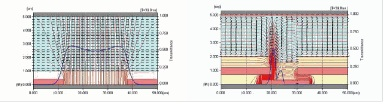
In the 2-dimensional calculation, spatial distributions of the director are calculated moment by moment as shown in the structural model below.
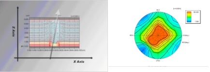
For the acquired director distribution, this option performs the calculation for the light passing through a cell as indicated by the arrow in the figure below. For electrode and dielectric layers other than liquid crystal, either isotropic materials or complete absorbers must be specified. When isotropic materials are specified, their refractivity and absorptivity are taken from the specified LCD Master database. For optical elements other than electrode and dielectric layers, Black Masks can also be defined at the top of the cell as necessary. In addition, the calculation can also be performed by aligning polarizers and phase compensation films, entered with the basic system, above and under the cell.
For the optical model defined in the above manner, an optical calculation will be performed with either the 2×2 or 4×4 algorithms. Since data can be scanned in the X-axis direction at each observation point, the distribution of the transmissivity in the X-axis direction can be obtained. In addition, since the azimuth and polar angle direction can be scanned, iso-luminance contour at that point can also be observed.
This calculation can be performed independently for each user-defined time data. For example, equal contrast contour can be observed for the spatial average of transmissivity at the OFF time and the ON time by acquiring the ratio between them.
As described in the Overview, with the optical calculation performed here, up to 20 optical films can be defined outside a liquid crystal cell. These films are assumed to have the same thickness and be applied in the X-axis direction. A light enters the films and the glass substrate to reach the cell. When the light propagates diagonally through the cell, the liquid crystal director on the path is extracted and calculated. The light coming out of the cell will reach the observation point after passing the glass substrate above and the films.
Mueller matrix
Newly an optical calculation function by Mueller matrix is added in .Ver.8 to the conventional optical calculation which was expressing polarization propagation using Jones matrix.
By the new optical calculation by Mueller matrix, Ver.8 has the following new functions.
・De-polarization simulation can be done.
・Partial polarized light can be handled in the incidence polarization.
・The actual data measured by OPTIPRO can be inserted to the database and calculated.
・The polarization data of the light source measured by OPTIPRO can be specified as an incidence polarization.
3DTV evaluation
It can stack optical materials at the observational point as an observational panel as well as conventional LCD panel defined on the basis of the absolute coordinate.
Especially it is very useful for design 3D TV eye-glasses. You can estimate the final optical quality via the eye-glasses by this function. As the observational panel can be saved into a disk as a sub-structural data, you can evaluate the performance in combination with other conventional LCD panel immediately.
Working with the ray-tracing software
It can import calculated result by which SPEOS (French company OPTIS) or LightTools(American company ORA)generate. Luminance and contrast ratio can be evaluated in radiometry or photometry.
Blue phase LCD analyzing
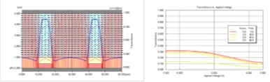
We developed a new software package for modeling the electro-optical response of blue phase liquid crystal displays (BP LCDs). The package, solving numerically the potential equation, finds the electric field that is generated by application of voltage to the electrodes in the BP LCD cell. Next it calculates the optical response or the polarization transfer characteristics of a BP LCD. We approximate the induced birefringence of BP LC by Kerr effect. The polarization transfer property is calculated numerically in the same way as in our LCD Master 2S package. Those results are shown graphically.
-The numerical calculations are carried out by the finite difference method (FDM) in the two dimensional space.
(cross section of an LC cell)
-Optical characteristics such as a distribution of transmittance along the transverse direction are shown graphically.
-The viewing characteristics such as angular dependence of contrast ratio are easy to evaluate by the viewing cone.
-The model of BP LCD cells are able to be defined easily and quickly through drag and drop operation in the GUI.